Materials
Accurately modelling the appearance of materials in a scene is crucial to obtaining a realistic rendered image. Indigo features a number of different material types, each customisable with various attributes, allowing great flexibility in material creation.
The material previews have been rendered in the main Indigo application (File -> New Material) using the default material ball scene.
Material Attributes
Indigo materials can have a number of attributes or parameters to control their appearance. Some of these are relatively common and simple, such as the Albedo parameter, however others such as Absorption Layer Transmittance are particular to a material type and warrant a detailed explanation.
Many of the parameters can be given either as a constant, a texture, or an ISL shader.
Albedo
Albedo can be thought of as a basic "reflectivity colour" for a material.
For example, if a material has an RGB albedo with each component set to 0.0, it will be completely black and reflect no light; with each component set to 1.0, light would never lose energy reflecting off the material, which is physically unrealistic.
A comparison of various albedo values found in nature is available on Wikipedia.
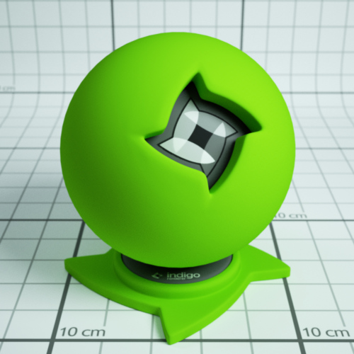
An example diffuse material with a green albedo.
Materials which have an albedo attribute:
Bump
Bump mapping gives the illusion of highly detailed surface without actually creating more geometry; in other words, it's a shading effect which gives a good approximation to more a detailed surface.
When specifying a texture map, the texture scale (B value) tells Indigo how far the distance is from full black to full white in metres. Since bump mapping is only intended to simulate small surface features, this value will be quite small since it is specified in metres, usually on the order of about 0.002.
See the Texture Maps section for information on texture attributes.
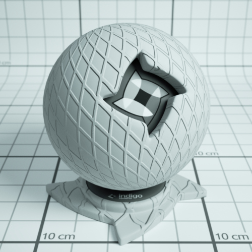
An example material with a grating texture used as a bump map.
Materials which have a bump attribute:
Diffuse
Phong
Specular
Oren-Nayar
Glossy Transparent
Displacement
Unlike bump mapping, which is a shading effect and does not create actual geometry, displacement mapping correctly generates new geometry from a base mesh and specified displacement map, by displacing the mesh vertices along their normals according to the displacement map.
This ensures that object silhouettes are correctly rendered, and is recommended for large displacements where bump mapping would look unrealistic; even mountain ranges can be efficiently created with this technique.
A constant setting displaces the entire mesh evenly by the defined amount. A texture map displaces the vertices based on values in a grey-scale image.
See the Texture Maps section for information on texture attributes.
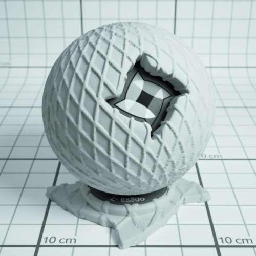
An example material a grating texture displacement map.
Materials which have a displacement attribute:
Diffuse
Phong
Specular
Oren-Nayar
Glossy Transparent
Diffuse Transmitter
Roughness
The roughness parameter controls the roughness of the surface, with lower roughnesses corresponding to a smoother, more polished surface with mirror-like reflections.
The roughness varies from zero to one, and it can be set using a texture or a shader.
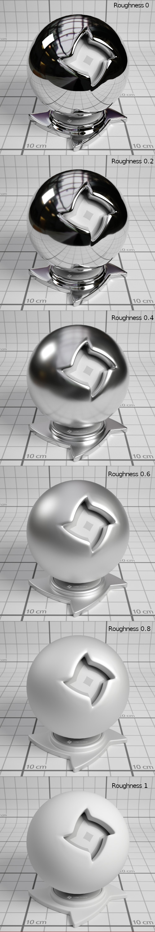
Example of Phong materials with different roughnesses.
Materials which have a roughness attribute:
Phong
Glossy Transparent
Coating
Double-sided Thin
Base Emission
This parameter specifies the base amount of light a material emits (in units of Lumens), which can be modulated using the Emission parameter.
This is used to create light sources.
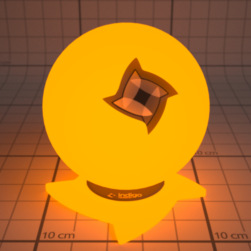
An example of a 1500 Kelvin blackbody emitter.
| RGB: | Light based on colour and brightness. |
| Uniform: | A white light with intensity based on value given. |
| Blackbody: | Light is based on the temperature. Measured in Kelvin. |
| Peak: | Defines a band of wavelengths in which the material emits light. |
| Tabulated: | The emission spectrum is specified at regular wavelength intervals, which is useful for entering lab-measured data when a very controlled simulation is required. |
Materials which have a base emission attribute:
Diffuse
Phong
Specular
Oren-Nayar
Glossy Transparent
Diffuse Transmitter
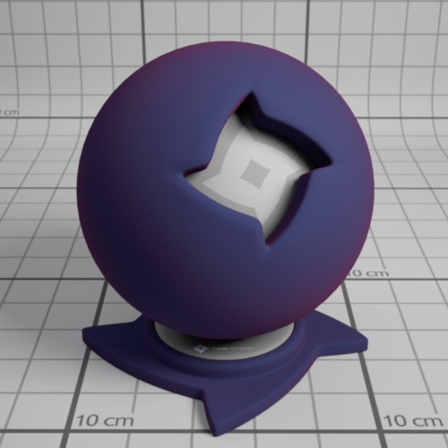
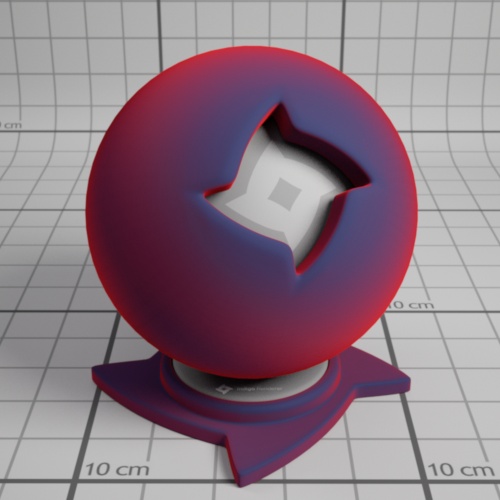
Emission
The emission parameter multiplies the Base Emission to produce effects such as TV screens, where the brightness varies over the surface of the screen.
An emission scale parameter is available to scale the emission of the material by a given amount. Various photometric units are available.
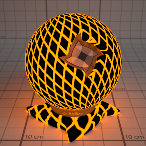
An example material with a 1500 Kelvin blackbody emitter, modulated by a grating texture.
Materials which have an emission attribute:
Diffuse
Phong
Specular
Oren-Nayar
Glossy Transparent
Diffuse Transmitter
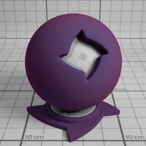
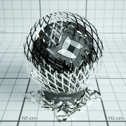
Absorption Layer Transmittance
Absorption Layer Transmittance refers to the absorption of light at the transmitting surface by a given "layer", which allows further control over how specular materials appear without changing the medium's absorption properties (which is what usually creates the perceived colour).
This can be useful for producing a stained glass window effect for example.
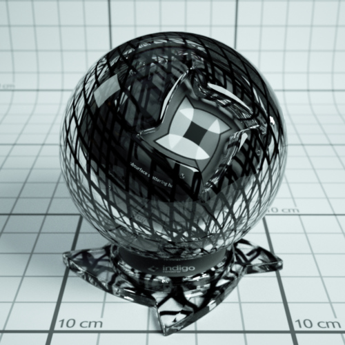
An example material with a grating texture used as an absorption layer.
Materials which have an absorption layer attribute:
Specular
Glossy Transparent
Layer
Light layers enable a rendered image to be split into additive "layers", in which each layer holds some contribution to the final rendered image.
How much a layer contributes to the final image can be adjusted interactively while rendering without restarting the process, and even after the render is completed, allowing for great flexibility in adjusting the lighting balance without having to do a lot of extra rendering. See Light Layers for more information on this subject.
The material's layer parameter specifies which light layer the (presumably light-emitting) material's contribution is added to.
Materials with attribute:
Diffuse
Phong
Specular
Oren-Nayar
Glossy Transparent
Diffuse Transmitter
Material Types
This section covers the various material types available in Indigo.
There are also video tutorials available for editing materials within Indigo, which include explanations of the material types, available here.
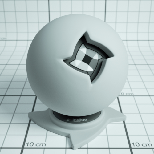
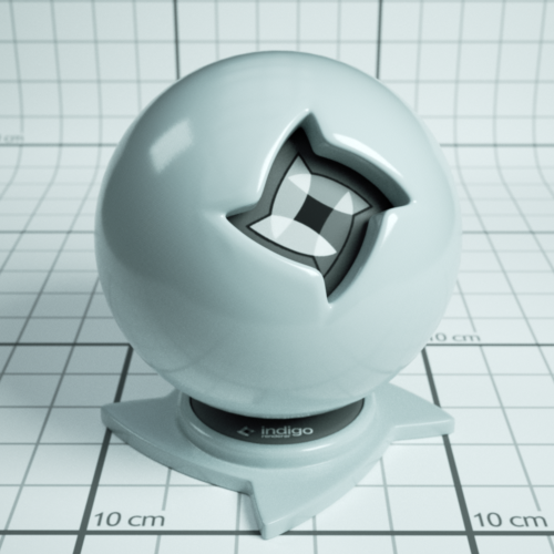
Diffuse
Diffuse materials are used for rough or "matte" surfaces which don't have a shiny appearance, such as paper or matte wall paint.

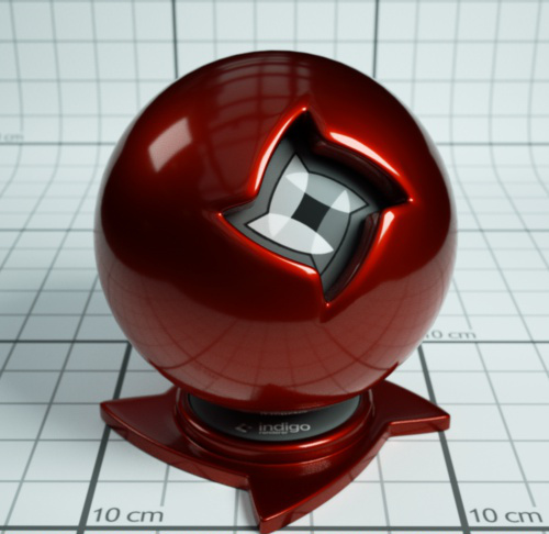
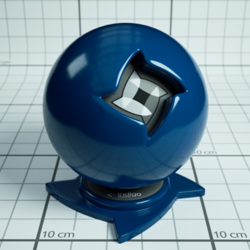
Phong
The Phong material is a generalisation of the Diffuse material type, adding a glossy coating on top of the diffuse base (or "substrate"). The influence of this coating is controlled by its index of refraction (IOR), with higher values corresponding to a stronger specular reflection. (the default IOR is 1.5)
It is commonly used for materials such as polished wooden floors, car paints (when multiple Phong materials are blended together) and metals.
Metals in particular can be represented using either the "specular reflectivity" option (which allows a specular colour to be defined for the material), or via measured material data (referred to as NK data).

IOR (Index Of Refraction): Controls the influence of the glossy coating; higher values produce a stronger specular reflection. The IOR should be set to the real-world value for the material, if available.
For example, the IOR of plastics is around 1.5 to 1.6.
Oil paint binder has an IOR of around 1.5.

Phong material with IOR 1.2

Phong material with IOR 1.5

Phong material with IOR 2.5
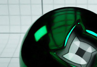
NK data: The Indigo distribution comes with a set of lab-measured data for various metals. If one of these data sets is selected, the diffuse colour and specular reflectivity colour attributes are ignored.
Specular reflectivity colour: When not using NK data, this allows you to set a basic colour for the metal; this is useful for uncommonly coloured metals such as Christmas decorations.
 |
 |
 |
| Green specular colour | Au (gold) NK dataset | Al (aluminium) NK dataset |
Attributes:
Albedo
Bump
Displacement
Exponent
Base Emission
Emission
Layer
Specular
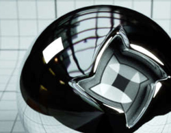
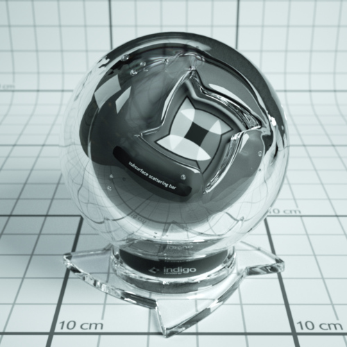
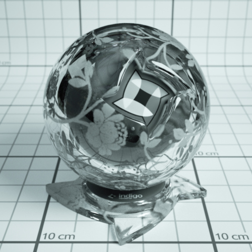
Specular materials are idealised materials which refract and/or reflect as in classical optics for perfectly smooth or flat surfaces (e.g. mirror-like reflection).
A specular material can either transmit light, as is the case with glass and water for example, or not as is the case with metals. This behaviour is controlled by the material's "Transparent" attribute.
If a specular material transmits light, it will enter an internal medium whose properties define the appearance of the material (such as green glass, which has absorption mainly in the red and blue parts of the spectrum). For more information on this please see the correct glass modelling tutorial.
Transparent: If enabled, it allows light to pass through the material. Otherwise only reflected light is simulated.
Attributes:
Albedo
Bump
Displacement
Base Emission
Emission
Absorption Layer Transmittance
Layer
Internal Medium
Oren-Nayar
Oren-Nayar materials are another generalisation of the basic diffuse material type, except unlike Phong which generalises to shiny surfaces, Oren-Nayar generalises to rougher materials.
The appearance is quite similar to diffuse materials, but with less darkening at grazing angles; this makes it suitable for modelling very rough or porous surfaces such as clay or the moon's surface.
Sigma: Controls the roughness of the material. A higher sigma gives a rougher material with more back-scattering. The default sigma value is 0.3, and values higher than 0.5 primarily cause energy loss / darkening due to strong inter-reflection. A value of 0.0 corresponds exactly to diffuse reflection.
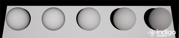
From left to right: Diffuse material, then Oren-Nayar with sigma values 0.0, 0.2, 0.5, 1.0.
Glossy Transparent
The glossy transparent material is a generalisation of the specular material, to allow non-perfect (i.e. rough) reflection and refraction, via an exponent parameter as with the Phong material.
It is commonly used for materials such frosted glass or even human skin (with a low exponent value).
![]()
Attributes:
Exponent
Internal Medium
Absorption Layer Transmittance
Bump
Displacement
Base Emission
Emission
Layer
Diffuse Transmitter
The diffuse transmitter material simulates a very rough transmitting material, which reflects no light back outwards. For this reason it is normally blended with a normal diffuse material to model surfaces such as curtains or lampshades.
It is meant to be used on single-layer geometry, and although it does not have an associated internal medium by default, it is possible to use one.
![]()
An example of the diffuse transmitter material on its own.
![]()
A blend between diffuse transmitter and normal diffuse materials to simulate the appearance of a curtain.
Attributes:
Albedo
Displacement
Base Emission
Emission
Layer
Blend
The blend material type isn't a material per se, rather it combines two sub-materials using blending factor.
This blending factor is a regular channel, and so can be constant, a texture or an ISL shader, allowing for great flexibility in material creation; a blend material can also use a blend as input, enabling so-called "shading trees" of arbitrary complexity.
Note that it's not possible to blend any combination of null and specular materials, except for the case where two specular materials with the same medium are being combined.
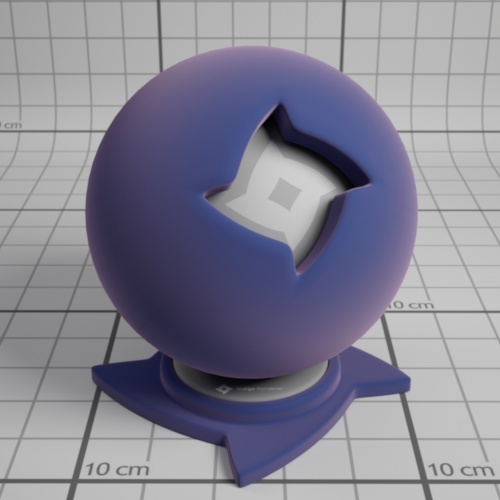
An example blend material from the material database, showing a blend between specular and diffuse materials.
Blend: Controls the amount of each material used. A value of 0 means only Material A is used, a value of 1 means only Material B is used, 0.5 implies a 50/50 blend, etc.
Step Blend: Instead of allowing partial blends, only one of Material A or Material B are selected, depending on whether the blending factor is below or above 0.5, respectively. This is recommended for "cut-out" clipping maps (such as for tree leaves), which produce less noise using this technique.
Exit Portal
When rendering interior scenes, one frequently encounters an efficiency problem where the "portals" through which light can enter the scene from outside (e.g. an open window) are relatively small, making it quite difficult to sample.
Exit portals can greatly improve rendering efficiency in these situations by marking important areas through which light can enter the scene, which Indigo will directly sample to produce valid light carrying paths.
Although it is a material type, exit portals don't have any particular appearance of their own, they simply provide an "open window" through which the background material is seen, and through which it can illuminate the scene.
For more information and example images, please see the SketchUp exit portal tutorial.
Requirements for exit portal usage:
- If any exit portals are present in the scene, then all openings must be covered by exit portals.
- The face normals must face into the interior of the scene.
- The exit portal material should only be applied to one side of a mesh (e.g. a cube), otherwise it will lose its effectiveness.
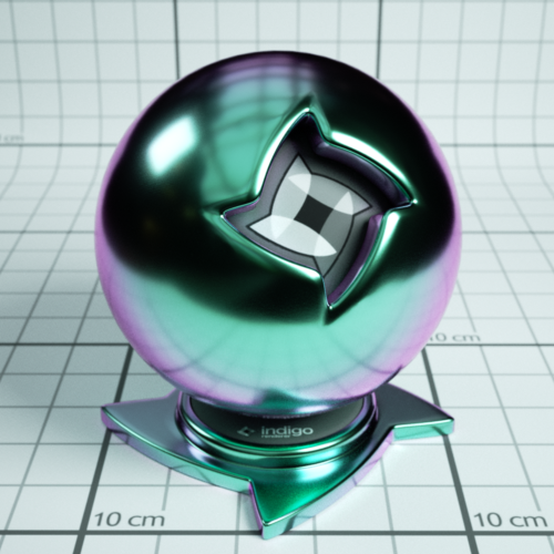
Coating
The coating material simulates a thin coating of some kind of material over another material. For example, you can create a thin coating of varnish over a metal material.
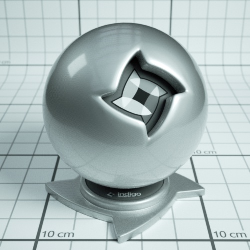
A coating material over a metal metal
The coating material can also simulate interference, which can give interesting effects when the thickness of the coating varies with position:
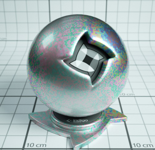
A coating material over a metal metal with interference enabled. Coating thickness is controlled with a shader.
Depending on the thickness of the coating, and how the thickness varies over the object (which can be controlled by a shader) you may get a kind of rainbow effect, or the material may just take on just a few colours:
400 nm thick coating showing colours from interference.
A coating can also absorb light, which will result in a tinted colour:
Coating with absorption over a metal material. The red colour comes from the absorption of non-red light as light passes through the coating layer.
Coating material attributes
Absorption
Controls the absorption of light as it travels through the coating layer.

Coating without absorption

Coating with absorption
Thickness
Controls the thickness of the coating layer. In the Indigo graphical user interface, the thickness is given in units of micrometres (μm), or millionths of a metre.
A thicker layer will have stronger absorption.
Coating with absorption, thickness of 100 μm.
Coating with absorption, thickness of 10000 μm.
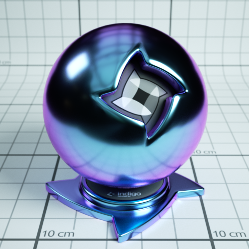
Interference
If enabled, thin film interference is computed for the coating layer.
The result will be most noticable when the coating layer is on the order of 1 μm thick.

Coating without interference, thickness 0.6 μm.
Coating with interference, thickness 0.6 μm.
Double-Sided Thin
The double-sided thin material is useful for modelling thin objects, such as paper or plant leaves.
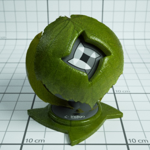
The double-sided thin material uses two 'child' materials: the front material and the back material, which are used for the front and back of the surface respectively. This means that you can make, for example, a leaf material where the front uses a different texture from the back.
It is also possible to specify the transmittance colour, which controls how light is absorbed and coloured as it passes through the object.
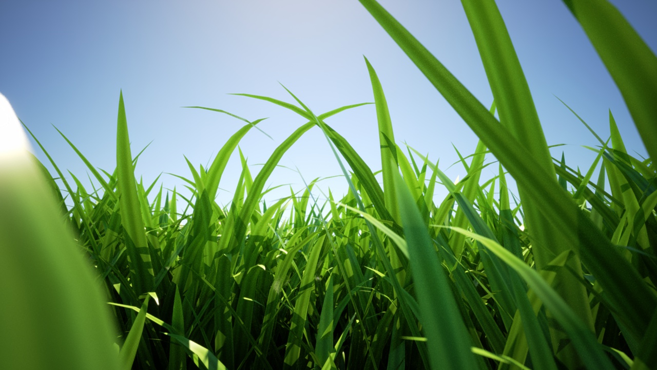
Render using double-sided thin material by Enslaver
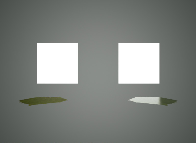
Leaf example
When the leaf is lit from the front, you can see that the leaf colour differs based on if the leaf is front or back side towards the camera: (The leaf on the right has the front/top side towards the camera) The light is behind the camera.
.jpg)
Leaf lit from front
When lit from the back, the leaf looks the same from both the front and the back. This is also what happens with a real leaf (try it!)
.jpg)
Leaf lit from back
The roughness (exponent) of the top can be varied independently of the roughness of the bottom of the leaf.
In this render the leaf on the right is frontside-up, on the left backside-up:
Leaf lit from top
Double-sided Thin Attributes
IOR: This is the index of refraction of the thin slab.
Front material: For light that is reflected diffusely back from the front surface, the front material controls the distribution of such light. Should be diffuse or Oren-Nayar. This material would be, for a leaf example, a diffuse material using the front-side albedo texture of your leaf.
Back material. For light that is reflected diffusely back from the back surface, the back material controls the distribution of such light. Should be diffuse or Oren-Nayar. This material would be, for a leaf example, a diffuse material using the back-side albedo texture of your leaf.
r_f: this is the fraction of light that enters the slab that is reflected back to the side it came from.
A good default value is 0.5
Transmittance: Some light scatters right through the slab and out the other side. The transmittance controls the absorption of such light. This is where you would use, for example, your transmittance map of a leaf.
Front Fresnel scale: A factor that controls the intensity of the specular scattering off the front interface of the slab. Default value is 1.
Back Fresnel scale: A factor that controls the intensity of the specular scattering off the back interface of the slab. Default value is 1.
Front Roughness: Controls the roughness of the front interface of the slab.
Back Roughness: Controls the roughness of the back interface of the slab.
Fabric
The Fabric material is useful for modelling textiles, such as cotton, wool, velvet etc. It is similar to a diffuse material except the edges of the material appear a different colour. This simulates forwards and backscattering due to small hair fibres.
Fabric Material Attributes
Colour: This is the main colour of the fabric. As usual it can be a constant colour, a texture, or a shader.
Roughness: This controls the roughness of the surface. A rougher surface will have a wider sheen 'highlight'.

Roughness = 0.1
Roughness = 0.9
Sheen colour. This is the colour of the sheen. The sheen is generally backscattered light, seen around edges of the objects.
For example, this fabric material uses a red sheen colour: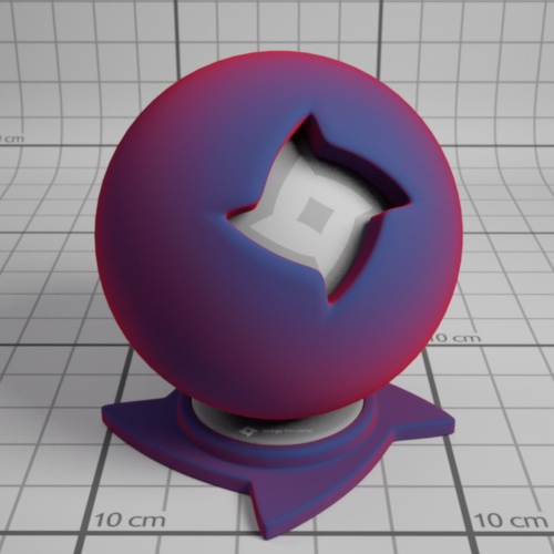
Sheen weight: This is the strength of the sheen reflection.
Sheen weight = 0.1
Sheen weight = 0.9
Null
The null material is not a normal material type (like the exit portal material), but rather indicates that light should pass straight through it, unaffected in brightness and direction.
This on its own is not very helpful, however when combined with the blend material type it becomes very useful for making "cut-outs" such as leaf edges, which would otherwise highly complex geometry.

An example of the null material on its own.
An example of the null material blended with a Phong metal, using a grating texture as blend map.
Texture Maps
Texture maps are a standard way of adding fine surface detail without adding more geometry. Indigo supports texture maps in many file formats, which are listed here.
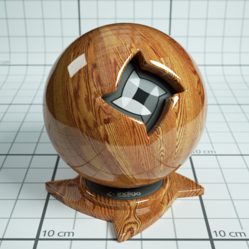
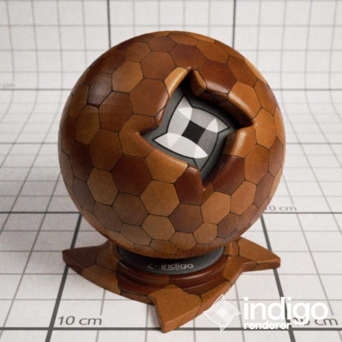
An example Phong material with a wood texture applied.
Supported texture formats:
| JPEG | .JPG .JPEG | Greyscale, RGB and CMYK are supported. |
| PNG | .PNG | Greyscale, greyscale with alpha, RGB and RGBA are supported. 8 bits per channel and 16 bits per channel supported. |
| Truevision Targa | .TGA | Greyscale (8 bits per pixel) and RGB (24 bits per pixel) are supported. |
| Windows Bitmap | .BMP | Greyscale (8 bits per pixel) and RGB (24 bits per pixel) are supported. Compressed BMP files are not supported. |
| OpenEXR | .EXR | 16 bits per channel and 32 bits per channel are supported. |
| TIFF | .TIF .TIFF | Greyscale, RGB, RGBA are supported. 8 bits per channel and 16 bits per channel supported. |
| GIF | .GIF | Supported. Gif animation is not supported. |
| RGBE | .HDR | Supported. |
Additional options:
| UV set index | Index of the set of uv coordinates used for texture maps. Usually generated by your 3D modelling package. |
| Path | Path to the texture map on disk. The path must either be absolute, or relative to the scene's working directory. |
| Gamma (exponent) | Used for converting non-linear RGB values (e.g. sRGB) to linear intensity values. A typical value is 2.2, corresponding to the sRGB standard. |
ABC values / texture adjustments
Often you'll want to change a texture's brightness or contrast in the rendered image, without having to modify the texture map itself.
During rendering, Indigo modifies the source texture data according to a quadratic formula with 3 parameters, A, B and C:
y = ax² + bx + c
x is the input value from the texture map, and y is the output value.
As a quick example for how this equation works: If we use A = 0, B = 1, C = 0 then the value is completely unchanged; this is therefore also the default.
A value – Quadratic
The A value scales the contribution of the quadratic (x²) term. This is typically not used, however it can be useful to adjust the contrast of a texture, with a value greater than 0, and/or a negative C value.
B value - Scale/Multiplier
Texture Scale (B value) of 2.
The B value scales the contribution of the linear (x) term. This is typically used to adjust the overall brightness (for example to reduce the maximum albedo of a texture, using a value of 0.8 or so), and can also be useful to adjust the contrast of a texture, with a value greater than 1, and/or a negative C value.
C value – Base/Constant
Texture constant (C value) of 0.2.
The C value is always added, regardless of the input texture amount; it therefore acts as a base or "floor" value. So for example if you have a completely black texture, and a C value of 0.5, it would appear as 50% grey.
Internal Medium
A (transmission) medium defines the properties of the matter through which light travels, when it is refracted at a material interface.
For example, a green glass medium will specify moderate absorption in the red and blue parts of the spectrum, so as to leave behind mainly green light; clear blue water will specify a small amount of absorption in the red and green parts of the spectrum so as to leave behind mainly blue light. If the medium contains many small particles, such as milk, then it will also specify other properties such as the scattering coefficient, etc.
- The object has to be a closed volume. This means it cannot have any holes leading to the interior of the mesh.
- All mesh faces must be facing outwards. Check the face 'normals'.
Precedence: Precedence is used to determine which medium is considered to occupy a volume when two or more media occupy the volume. The medium with the highest precedence value is considered to occupy the medium, 'displacing' the other media. The predefined and default scene medium, 'air', has precedence 1.
Basic
Typical values for glass and water lie in the range 0.003 – 0.01 (see http://en.wikipedia.org/wiki/Cauchy%27s_equation for some coefficients)
| IOR | Index of refraction. Should be >= 1. Glass has an IOR (index of refraction) of about 1.5, water about 1.33. The IOR of plastic varies, 1.5 would be a reasonable guess. |
| Cauchy B Coeff | Sets the 'b' coefficient in Cauchy's equation, which is used in Indigo to govern dispersive refraction. Units are micrometers squared. Setting to 0 disables dispersion. Note: the render can be slower to converge when dispersion is enabled, because each ray refracted through a dispersive medium can represent just one wavelength. So only set cauchy_b_coeff to other than 0 if you really want to see dispersion. |
| Absorption Coefficient Spectrum | Controls the rate at which light is absorbed as it passes through the medium. |
| Subsurface Scattering | Use this element to make the medium scatter light as it passes through it. |
| Scattering Coefficient Spectrum | Chooses the phase function used for the scattering. |
Phase Function
The phase function controls in which direction light is scattered, when a scattering event occurs.
| Uniform | Takes no parameters |
| Henyey Greenstein | The Henyey-Greenstein phase function can be forwards or backwards scattering, depending on the 'g' parameter. |
Dermis
| Hemoglobin Fraction | Controls the amount of hemoglobin present. Typical range: 0.001 – 0.1 |
Epidermis
Medium for simulating the outer layer of skin.
| Melanin Fraction | Typical range: 0 – 0.5 |
| Melanin Type Blend | Controls the amount of eumelanin relative to pheomelanim in the tissue. Typical range: 0 – 1 |
Material Database
The online material database is located at http://www.indigorenderer.com/materials/
There you are able to browse and download any of the user uploaded materials, and upload your own.
Please note that you cannot upload textures that you do not have the right to redistribute.
Indigo Shader Language
A fully procedural material made by galinette.
ISL stands for Indigo Shader Language. It's a functional language that allows you to write shaders for every channel in Indigo materials. With shaders you are not tied to the restrictions of textures any more: they are procedurally computed for every point on the surface.
Indigo Shader Language Beginner Tutorial
Indigo Shader Language Beginner Tutorial
This tutorial covers:
-What's ISL? And why should I use it?
-What's a functional language?
-How to define functions
-Which channel expects what function parameters an return value?
-What data-types are there?
-Functional, huh? Does that mean I have to use functions instead of operators?
-How to use a shader in a material?
-Going further
What's ISL? And why should I use it?
ISL stands for Indigo Shader Language. Its a functional language that allows you to write shaders for every channel in Indigo materials. With shaders you're not tied to the restrictions of textures any more because they are procedurally computed for every point on the surface (or in the volume, as of Indigo 2.4's ability to have volumetric shaders).
What's a functional language?
In functional language there are only functions that are used to compute something, no variables no loops (unless you write them as a function). By functions it means functions in the mathematical sense, it calculates something and returns the result. Lets have a look at this shader function: def doSomething(vec3 pos) real: noise(fbm(pos * 3.0, 8)) This is a function called 'doSomething', it has one parameter, a vector called 'pos' and it returns a real value. It uses two other functions, fbm() and noise().
Now what's happening here?
Like in a mathematical function you calculate the innermost parenthesis first. That means the vector 'pos' is multiplied by 3.0, then passed to the fbm() function which calculates a value of the type 'real', which is then passed to the function noise(), which calculates a 'real' value, which is the return value of the function 'def'. Pretty simple, isn't it?
How to define functions
Now, lets see how to define a function. A ISL function definition always starts with the keyword 'def', needs at least a name and a return value type, and it can also have function parameters: def name(parameters) return_value_type: [...actual function...] Although you can give your functions an any name you want the main function in a channel always has to have the name 'eval'. Which takes us directly to the next topic: different channels expect different parameters and return values!
Which channel expects what function parameters an return value?
There are three different channel types, wavelength dependent, wavelength independent and displacement. Wavelength dependent expects a vec3 as a return value, wavelength independent expects a real and displacement expects real and cannot use the position in world-space (vec3 pos) as a function parameter. Here's a table that illustrates all that: C
|
Channel |
Channel type |
Eval function expected |
|
Diffuse |
Wavelength dependent |
def eval(vec3 pos) vec3: |
|
Emission |
Wavelength dependent |
def eval(vec3 pos) vec3: |
|
Base Emission |
Wavelength dependent |
def eval(vec3 pos) vec3: |
|
Specular Reflectivity |
Wavelength dependent |
def eval(vec3 pos) vec3: |
|
Absorption Layer |
Wavelength dependent |
def eval(vec3 pos) vec3: |
|
Exponent |
Wavelength independent |
def eval(vec3 pos) real: |
|
Sigma |
Wavelength independent |
def eval(vec3 pos) real: |
|
Bump |
Displacement |
def eval() real: |
|
Displacement |
Displacement |
def eval() real: |
|
Blend |
Displacement |
def eval() real: |
What data-types are there?
First of all, its very important to know that ISL does not convert values implicitly, so if a function expects an integer, you have to make sure you give pass an integer value instead of a real.
-
real – floating point number
A real value always has to be written as a floating point number, for example 214.0.
-
int – whole numbers
Only whole numbers, like 20 or -1545.
-
vec3 – 3 component vector
There are two constructors for a vec3, vec3(real x) and vec3(real x, real y, real z). The first one applies the number passed to any of the 3 components and the second one sets each component separately. You can access the three components separately with the functions doti(), dotj() and dotk().
-
vec2 – 2 component vector
Like vec3, only just 2 components.
-
bool
A boolean value, true or false.
-
mat2x2 and mat3x3
2x2 and 3x3 matrix, I'm not going to talk about these right now.
Functional, huh? Does that mean I have to use functions instead of operators?
No, you don't have to use functions as operators, but you can, if you like to, are a hardcore mofo or just a little insane :) Operators are available for multiplication, division, addition and subtraction (*, /, + and -, would you believe it?) for every data-type that supports them, but the order of operands is important sometimes, for example: 0.333 * vec3(5.2) will not work since it expects the vec3 first. Vec3(5.2) * 0.333 works. The equivalent functions are called mul(), div(), add() and sub().
How to use a shader in a material?
Your exporter most likely has an option to use ISL shaders, also, you can use ISL in the Indigo Material Editor it allows you to use ISL shaders. And if you're hardcore, you can edit the .igs file generated by you exporter and insert your shaders manually, here's how you do it: Open the .igs file and look for a material. I'll just assume we found a phong material:
<material>
<name>phong_mat</name>
<phong>
<ior>1.466</ior>
<exponent>
<constant>800</constant>
</exponent>
<diffuse_albedo>
<constant>
<rgb>
<rgb>0.588235 0.588235 0.588235</rgb>
<gamma>2.2</gamma>
</rgb>
</constant>
</diffuse_albedo>
</phong>
</material>
What you have to do is, is to replace the <constant>...</constant> XML elements (and anything in between) in the diffuse_albedo channel with this:
<shader>
<shader>
<![CDATA[
#paste your shader in here, oh by the way: every line starting with # is a comment
)]]>
</shader>
</shader>
Then paste your shader in between '<![CDATA[' and ')]]>'.
Going further
For a complete list of all available functions, have a look at the ISL section in the 'Indigo Technical Reference.pdf' and the 'ISL_stdlib.txt' in the Indigo folder. Also, more ISL tutorials are coming!
Indigo Shader Language Tutorial
ISL stands for Indigo Shader Language, the language for creating procedural materials in Indigo. Since it's a functional language, it can be a bit tricky to create some patterns that are easy enough in an imperative language. For example, lets say you want to write a shader to make a polka-dot pattern. In an imperative language you might write some code like
def fillWithColour(background_colour):
	for(int x=0; x<W; ++x) {
		for(int y=0; y<H; ++y) {
			drawDot(x, y, dot_colour);
		}
	}
But in ISL, you can't do things this way. You have to write a function that returns the colour, and that depends only on the position and/or UV-coordinates of the current surface point being shaded, e, g:
def getColourForPoint(u, v):
	if( the point (u, v) is inside a dot ){
		return dot_colour
	} else {
		return background_colour
	}
This tutorial shows you how to use such a functional technique to create regularly repeating patterns, like polka-dots, with ISL.
Lets start by discussing the fract function.
As described in the Indigo Renderer Manual, fract takes a single real number, and returns a real number:
fract(x) = x - floor(x)
The useful thing about this function, is that it repeats regularly across the real number line, with period 1. We can use this function to create more complicated behaviour.
So lets say we want to create some stripes, such that they alternate in the U direction of the UV coordinates. Suppose we have a foreground and background colour.
Using the fract function above, we can can assign the foreground colour when fract(x) < C, and the background colour when fract(x) >= C, where C is some constant between 0 and 1. If C is 0.5, the stripes will have the same width as the background stripes.
Let's see how that looks in real ISL:
<material>
	<name>previewmaterial</name>
	<diffuse>
		<albedo>
			<shader><shader><![CDATA[
def eval(vec3 pos) vec3 :
	if(
		fract(doti(getTexCoords(0))) < 0.5,
		vec3(0.9, 0.0, 0.0), # Red
		vec3(0.2, 0.2, 0.2) # Dark Grey
	)
			]]></shader></shader>
		</albedo>
	</diffuse>
</material>
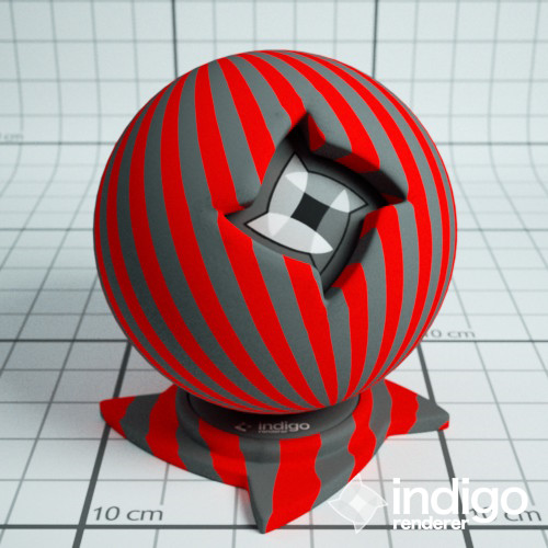
And the resulting render:

The shader with fract(x), so slowly repeating stripes.
In this example the foreground colour is red, and the background colour is dark grey. This example looks a bit weird because the stripes are large compared to the model. We can solve this problem by multiplying the UV coordinates by a number greater than one before we pass the value to fract, e.g we could use something like fract(10 * x)
The ISL is then:
def eval(vec3 pos) vec3 :
	if(
		fract(doti(getTexCoords(0)) * 10.0) < 0.5,
		vec3(0.9, 0.0, 0.0), # Red
		vec3(0.2, 0.2, 0.2) # Dark Grey
	)
And the resulting render is:
The shader with fract(10 * x) so more repeating stripes.
So, at this point in the tutorial, we have more-or-less solved the problem of how to create regularly-repeating patterns, at least with respect to the U coordinate (e.g. in one direction).