Tutorials
Modelling a pool in SketchUp
Introduction
In this tutorial I will show how to model a simple swimming pool in SketchUp and Indigo, with nice caustics at the bottom of the pool. This is what we will be making:

Model the pool ground and walls
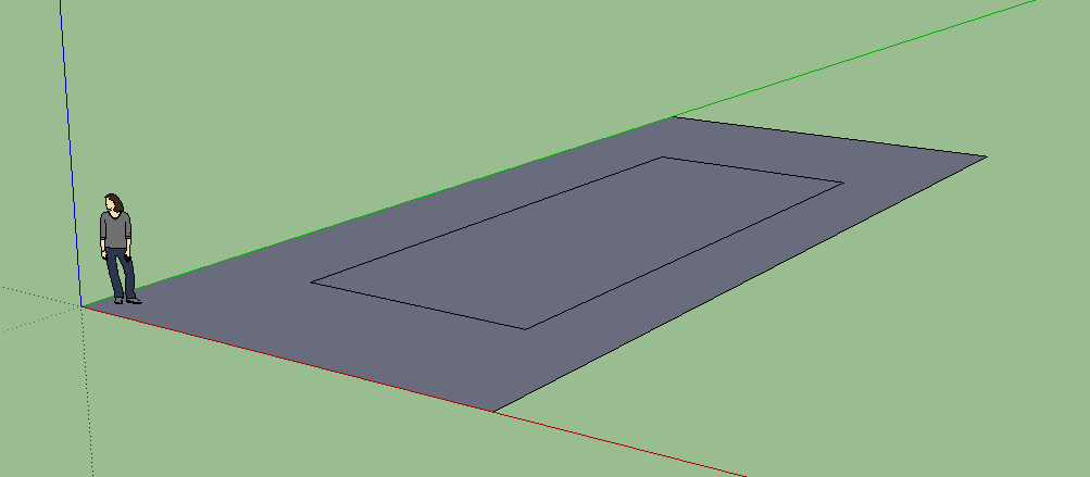
Create a quad like so:

Create a rectangle in the middle of the quad:
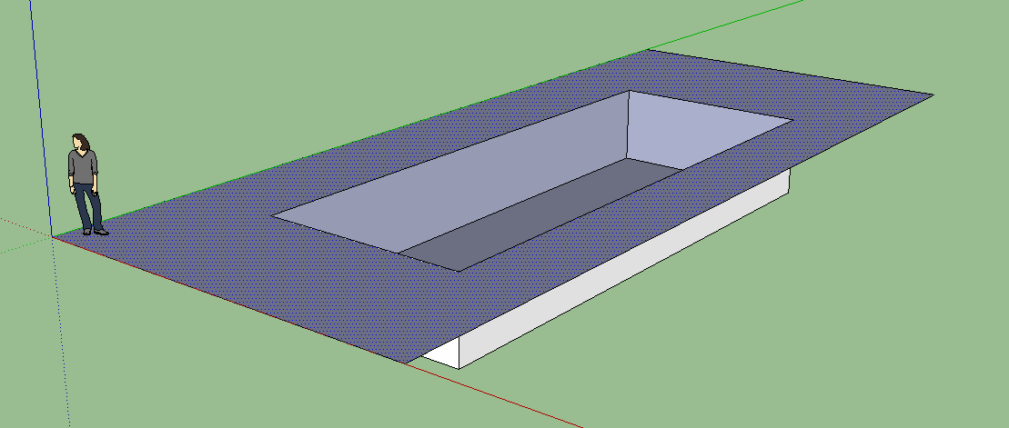
Using the Push/Pull tool, push the middle down to create the pool recess:
Create the water volume
Create a cuboidal volume for the pool water. It needs to be somewhat larger than the pool recess along all axes.

Create the water material
Create a new SketchUp material called 'water' or similar.
Set the opacity to something around 50% to make sure the water material is transparent.

Apply the material to all faces of the water volume.

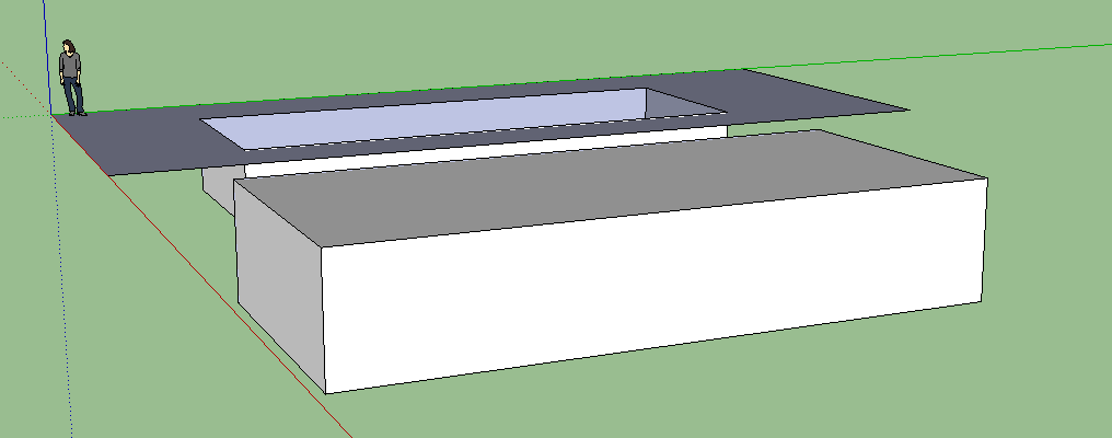
Move the water volume into place
Move the water volume into place with the move tool. The sides of the water volume should extend past the pool recess like so:

Finishing the water material
We need to set a couple of settings in the water material - some absorption to give the water a blue/green tint, and some displacement, to create the water ripples.
Open the SkIndigo material editor, and make sure the 'water' material is selected.
Change the material type to 'specular':
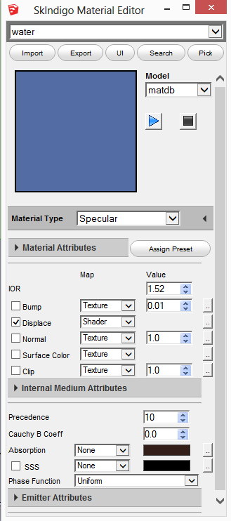
Change the Absorption type to 'none'.
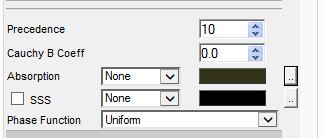
Click the dotted button to the right of 'Absorption'.
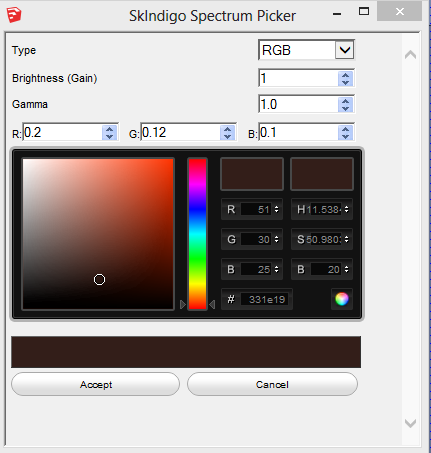
Set the RGB absorption to R: 0.2, G: 0.12, B: 0.1:
Now we need to create the displacement shader.
Check the 'Displace' checkbox in the SkIndigo material editor,and set the type to 'Shader'.
Now click on the dotted button to the right of 'Displace'.
Paste the following shader code in to the shader editor:
def eval() real :
fbm(posOS() * 2.0, 2) * 0.02
Like so:
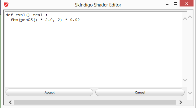
What this shader does is displace the water surface by up to 2 cm (0.02 m), based on some pseudo-random noise (fbm) based on the object-space position (posOS).
If you want to make the ripples higher, you an increase the 0.02 number.
If you want to make the ripples more closely spaced, you can increase the 2.0 number.
Setting subdivision on the water volume
We want to make sure that only the water volume mesh gets subdivided.
To do this, first make sure the entire water volume object is fully selected by triple-clicking on it:

Now right click on it, and choose 'Make Group'.
Now double-click on the group to select it. This should grey everything else out:

Now right click on the pool volume and choose 'Edit Active Mesh' from near the bottom of the menu. It should say something like 'Group#1 (6 faces)' at the top of the SkIndigo Mesh Settings dialog.
Set 'Max Subdivisions' to 8. This will turn each original quad face into 4^8 = 65536 subdivided faces.
Also un-check the 'View Dependent' checkbox, and set 'Curvature Threshold' to zero:

Make the final render
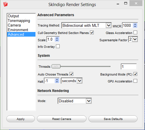
First off, we have to change the render mode to Bidirectional with MLT:
This is very important as it's the most efficient mode for rendering these kind of caustics.
Position the camera above the pool, then press the 'Render in Indigo' button.
After a while, you should get an image like this:
You may have to be a little patient waiting for the render - even with bidirectional MLT, it can still take a while.
Setting up interior lights mixed with sun+sky lighting
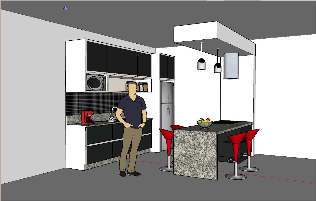
We will start with a kitchen scene, downloaded from the SketchUp 3d Warehouse, with some walls added:
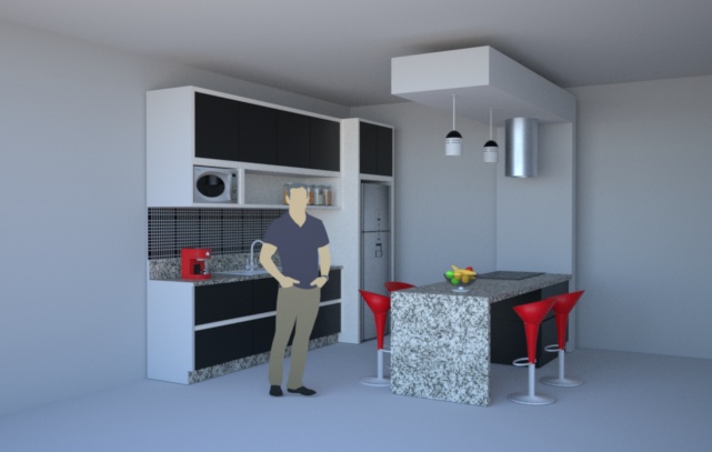
By default this will render in Indigo with Sun+sky illumination, resulting in a render like this:
We now want to set up the lights hanging above the bench so they emit enough light to be visible.
First off, we want to add a quad in each light fixture which will emit the light.
A single quad results in the most efficient rendering. The quad should not be too small (otherwise it will make specular reflections noisier). It is also important that the front side of the quad is pointing down - as in Indigo by default, light is emitted from the front side of a surface only.

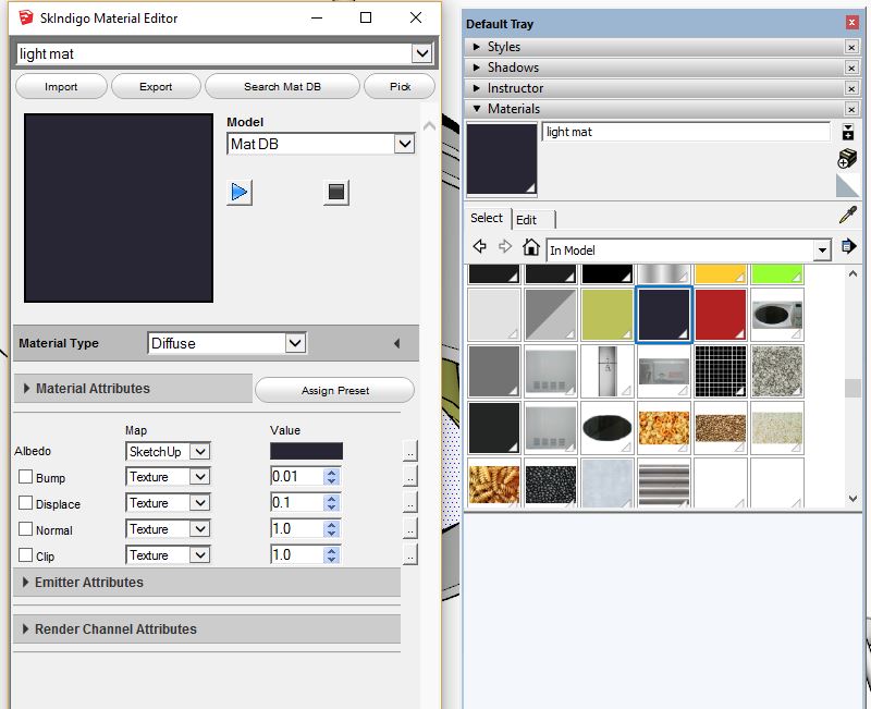
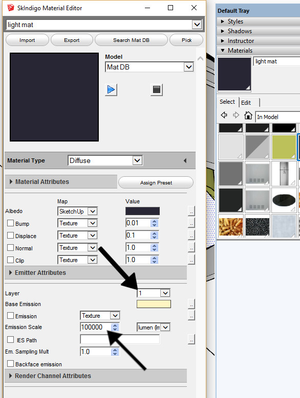
The next step is to create a new SketchUp material. I have called mine 'light mat'. Since I have the SkIndigo material editor open (you can open the SkIndigo material editor from the SkIndigo toolbar) it shows and allows me to edit the 'light mat'. You will also want to assign the your new material to the new quads you have created.
The next step is to edit your new material so it emits light.
You can do this by expanding the Emitter Attributes section, then setting the Layer to something like 1,
and setting the Emission Scale to something like 100000 lm.
Note that the emission scale needs to be very high for the light to be easily visible in daylight.
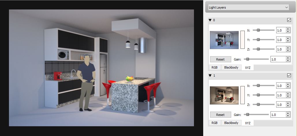
And that's all there is to it!
Since we put the interior lights on light layer 1, we can use the light layer controls in Indigo to view the contribution of the interior lights separately from the sun+sky lighting (see the layer thumbnails on the right):
Using exit portals in SketchUp
Introduction
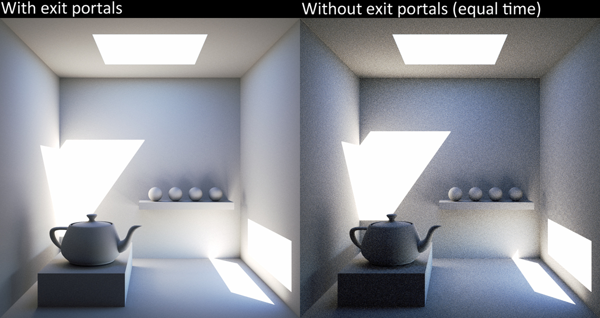
Exit portals (often abbreviated as EP) are a way for artists to assist the rendering engine in difficult lighting situations, by specifying a "portal" through which light will travel. These are very useful for interior renders, where there is a relatively small opening letting in a lot of light (such as a window) that is not easily accessed - in such scenes, there is often a dramatic increase in convergence speed (since light-carrying paths are much more easily constructed).
In the example below both images rendered for 5 minutes, the only difference being the presence or absence of exit portals (click to enlarge):
Requirements and limitations
There are several requirements for exit portals to work effectively:
- All openings through which light can "escape" (directly to the background or environment) must be covered with exit portals.
- The exit portal normals must point inwards.
- Bi-directional path tracing mode must be used.
Finally, note that nothing gets rendered behind an exit portal: when a light ray strikes the portal it is assumed to immediately "exit" or escape to the background / environment, without considering any other objects in the scene.
Modelling with exit portals
We now show how to convert a simply modelled room with an opening into a scene using exit portals in SketchUp. The scene below shows an interior space, illuminated only by two openings which allow sunlight in:

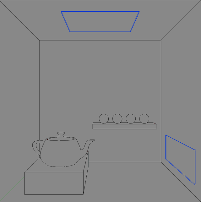
Next we create quads to cover the openings, corner to corner. There should be no gaps, and to really make sure this is the case it could be made slightly bigger than the opening and fitted inside to slightly intersect the surrounding geometry.
The next step is crucial to stop these quads being part of the surrounding geometry (and therefore sharing its material settings): select the quads to become exit portals, right click on them, and make them a group. You should see them marked as a blue group:
To turn them into exit portals, simply use the exit portal material type for the object.

With the exit portal created, we can now export to Indigo and enjoy the much faster convergence.
If Indigo reports an error such as "Error: Scene parsing error: Model (UID 42) has a different number of materials than geometry material references", it means that the exit portal quad was merged with the surrounding objects. This won't work because we need only the quad to be flagged as an exit portal.
Make sure that the front face of your exit portal object is pointing inwards into the scene!
You may need to flip the group along an axis to achieve this.
Thanks to Filippo Scarso / Pibuz for the example scene and helpful suggestions.
Using orthographic cameras with SketchUp
Introduction
Orthographic cameras remove the perspective effects normally seen in a 3D rendered image. This is sometimes desirable for technical illustration or architectural visualisation purposes.
In this tutorial we'll cover the steps required to render with orthographic cameras in SketchUp, as well as cover some potential pitfalls with their use.
Switching from perspective to parallel projection
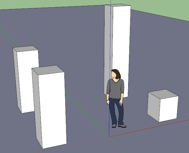
We start with the normal (perspective projection) camera, which will give the normal depth cues such as distant objects being smaller, in a simple scene with some boxes:
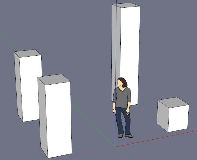
We now select the Parallel Projection option from the Camera menu, which will enable the orthographic camera mode:

With this applied, we can immediately see the viewport change to remove all perspective effects.
The zoom level may need adjusting to keep the same part of the scene in view; bear in mind that this is actually changing the camera's sensor size, so if you're rendering a building it will need a building-sized camera.
Pitfalls
Orthographic cameras require Indigo 3.4.4 or newer; earlier versions will report an error when attempting to render scenes which have a non-perspective camera defined.
The orthographic camera must be at least as large as the objects in view, since they are directly projected (parallel rays) without any perspective effects which might otherwise allow large objects in the distance to be viewed with a much smaller sensor.
One potential pitfall with large camera sensors is that they may intersect other scene geometry (e.g. go through walls), especially different media (e.g. go through glass or water), causing problems.
The former will result in open spaces between surfaces, which may or may not receive light, while the latter can be more problematic; Indigo currently (as of 3.4.8) assumes that the camera is in a single medium, which is usually a reasonable assumption, however with the large sensors sometimes used in orthographic rendering, this assumption is more likely to break down.
Using section planes in SketchUp
Introduction
Section planes allow you to create "cut-away" renders of scenes without having to change the (potentially complex) underlying geometry, using oriented planes to slice away obstructing sections from view. This is related to cut-away diagrams classically used in technical illustration.
In this tutorial we'll cover using SketchUp's section planes with Indigo version 3.4 or newer.
Adding and enabling sections
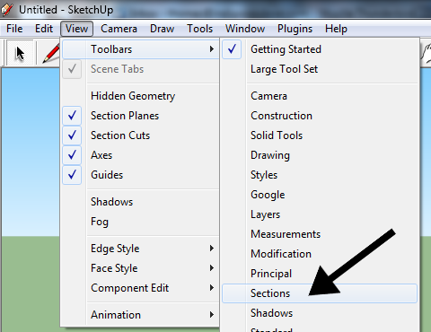
The first thing we'll need to do is enable the Sections toolbar if it is not already enabled; this can be done via the "View" menu, under "Toolbars" -> "Sections":
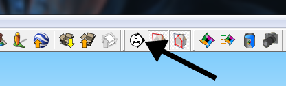
With these controls available, we can now add a section plane using the first tool on the toolbar (Section Plane):
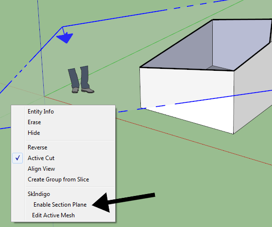
Once the plane has been placed and oriented as desired, we must right-click on it and select "Enable Section Plane" from the SkIndigo sub-menu:
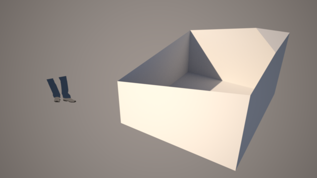
If we now render the scene with Indigo, we see that the section to the front of the section plane is rendered, and the rest has been clipped away:
Multiple section planes can be used together in this manner, to cut away whichever parts of the scene are obstructing an important interior view. There is no performance penalty for using one or many section planes, as they are processed at load-time; however, if a section plane intersects a complex mesh, it may require a considerable amount of extra memory to process during loading.
Pitfalls
If the section plane intersects any media in the scene, there is a chance that the medium definition will become inconsistent.
For example, if a glass pane is sliced by a section plane such that one of the sides is removed, the geometry containing the medium will be open, which can cause rendering problems.
Using the material database in SketchUp
This tutorial will cover how to download and use materials from the online material database using the SkIndigo exporter for SketchUp.
The Indigo Material Database can be found at http://www.indigorenderer.com/materials/
There are two ways to use materials from the online database in SketchUp/SkIndigo: loading directly into SketchUp, and externally linking to downloaded materials. We'll cover both options in sequence, starting with the simpler direct import method.
Importing directly into SketchUp
-
Creating a new SketchUp material
Let's start by opening SketchUp and making a simple object to apply the material to (in this case a cube). We'll also want to create a new SketchUp material (via Window menu -> Materials -> Create Material) to hold our Indigo material, and apply it to the newly created cube.

-
Opening the SkIndigo online material browser
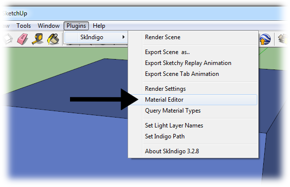
Having created a simple object and applied a new material to it, from the "Plugins" menu, under the "SkIndigo" sub-menu, select "Material Editor":
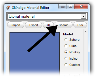
This opens the SkIndigo material editor window. At the top of the material editor window is a "Search" button, click this to open the material database window in SkIndigo:
-
Downloading and applying a material
The material database browser window will open, allowing you to search for materials by keywords or name. By default the most recently materials submitted will appear at the top:

If we choose a material and double click it, SkIndigo will ask if you'd like to load it into the currently selected material; click "Yes", otherwise it will want to save the downloaded material to disk.
The downloaded material should now be loaded into the SketchUp material and applied to your object, ready for rendering with Indigo:

Alternative method: Linked IGM
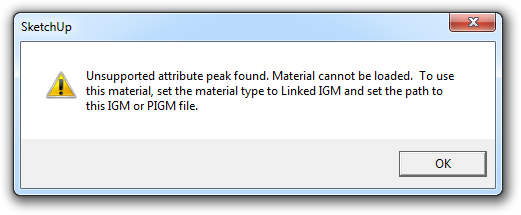
It is however possible, that the material cannot be represented properly within SketchUp, since it is not a physically-based renderer. In such situations, SketchUp will present a warning dialog suggesting it be used as a "linked" material:
-
Linking a downloaded material
To do this, we select the material in the SkIndigo material editor, and set its Material Type to "Linked IGM":
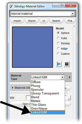
Click the ".." button next to the "IGM" field, and select a downloaded IGM or PIGM file. This will link the downloaded material to the SketchUp material so that when Indigo renders the scene, it will use the linked material.
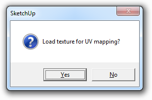
Since the material cannot be represented correctly in SketchUp, SkIndigo will prompt you for a texture to use for the material in the SketchUp viewport. This is so you can easily identify the linked material, however it is optional: